Satellite Communication - Transponder and Earth Station:
- Get link
- X
- Other Apps

Introduction: In my last communication blog: Basic concepts of Satellite Communication, I gave the basic idea of Satellite Communication for beginners. In that blog, I have explained the following Concepts: Satellite, Artificial satellite, Communication Satellite, Active and Passive satellite, Satellite Communication, Satellite Orbits (LEO, MEO, GEO, HEO, Circular, Elliptical, Polar, Graveyard), Look Angle (Azimuth and Elevation), Earth Coverage Angle, Inclined angle, Latency, Footprint, Satellite beam, slant range, Orbital slot etc. Readers are requested to go. Through that blog if they are Interested. In this blog, we will go ahead and Learn more about satellite communication. Here, we will Discuss the uses, frequency band, segments of satellite communication, etc. Use of Satellite Communication: Some uses are listed below: 1. Radio and TV broadcast. 2. Air, Ship, Land, and mobile communication. Air and Ship Communication is not possible Without the communication Satellite. 3. GPS, Tracking and Navigation. 4. Communication in remote areas where terrestrial communication is difficult or Impossible. 5. Military and Spying purposes. 6. Voice, data, and Internet communication. 7. Remote sensing and weather Forecast. 8. Research and experimental Use. 9. and many more. |
Working principle of Satellite Communication: Any voice call, data, or internet communication intended to go Through satellite, is multiplexed/processed at different stages before reaching The assigned earth station. After reaching Earth station, it is demultiplexed, bifurcated as per The structure of the Earth station, And further multiplexed and processed to make it compatible with transmitting from the Earth station through a satellite Antenna. After transmitting from Earth station, the signal is accepted by a Satellite receiving antenna in space. Thereafter it is processed In the different units of transponder (Communication devices of satellite) To make it compatible to be sent back to receiving earth stations through satellite transmit antenna. The signal transmitted from the satellite antenna is accepted by the assigned satellite earth station(s). The received signal is further processed here to retrieve the signal. After processing to make it compatible for distributions, it is transmitted to Different terrestrial links. If the receiving earth station is not in the coverage area (footprint) of this satellite, the The signal is transmitted from this satellite to another satellite (inter satellite communication) and later transmits the signal to the desired earth stations. The frequency with which the signal is transmitted from the Transmit Earth Station is called The Uplink frequency and the frequency with which the signal is transmitted from the satellite to The Earth station is called the Downlink frequency. |
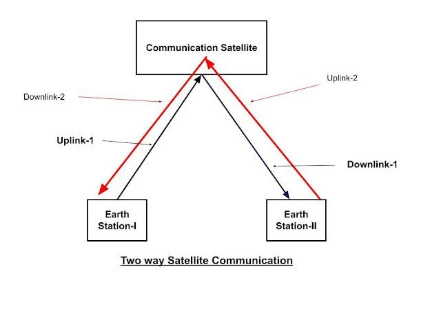
What services are provided by Satellite Communication? 1. One-way service - It is a broadcast service like TV channels. TV programmes are broadcasted from a transmit earth station and millions of Receive earth stations ( that are TVs etc.) across the world receive the program. Since our TVs are not sending any signals, just receiving the signals. So such a type of communication is called One-way service. 2. Two-way service- In this type of service, both ends exchange signals. So each earth station works as a Transceiver (Transmitter and Receiver: both). Just like our telephone service. It is shown in the following figure: |
Frequency bands suitable for satellite Communication: The basic idea of the frequency band used for satellite communication is summarized Below: |
30 Mhz to 300 Mhz VHF band: (Very High Frequency) Line of sight, short-distance communication for FM radio, air traffic, and security agencies. Data communication from weather satellites etc. |
300 Mhz to 01 Ghz UHF (Ultra High Frequency) Line of sight, short-distance communication for FM radio, air traffic, and security agencies. Data communication from weather satellites etc. |
01 GHz to 02 GHz L band: GPS, Mobile Satellite Service -MSS (INMARSAT, THURAYA etc.) Uplink frequency - 1.6 Ghz Downlink frequency - 1.5 Ghz |
02 GHz to 04 GHz S-band MSS and Aero Services (flight services), NASA, Deep space research, etc. |
04 GHz to 08 GHz C band Satellite Communication FSS (Fixed Satellite Services), TV broadcast services. Uplink frequency - 6 Ghz Downlink frequency - 4 Ghz (most popular) |
08 Ghz to 12 Ghz X band FSS, military purposes, etc |
12 GHz to 18 GHz Ku band FSS and Broadband Satellite Service (BSS) For higher bandwidth. Uplink frequency - 14 Ghz Downlink frequency - 12 Ghz (most popular) |
27 GHz to 40 GHz Ka-band FSS, BSS, Future communication. |
40 GHz to 75 GHz V band High-speed broadband services. |
As an example, a satellite has 500 Mhz bandwidth and a transponder has 40 Mhz bandwidth. So 12 transponders can be accommodated in a satellite. The remaining bandwidth of 20 Mhz is used as a guard band to avoid interference. In the real picture, bandwidth and number of transponders may be different for a satellite. |
Components of Satellite Communication: Mainly two components (Earth segment and Space segment ) carried out the satellite communication. Both Segments are described below: 1. Earth Segment or Ground Segment: Generally, it consists of Earth stations, TT&C, Control, and command center, etc. TT &C and Control and command center is explained at the end of this section. First, we will try to understand the working of an earth station. Mainly earth stations may be of three types: (I) Earth station (for Transmit only) - These are generally broadcast stations. They simply transmit the communication, not having any receiving system. (II) Earth station (for Receive only) - These are generally Television sets (DTH = direct to home) or similar devices. (iii) Earth station (for transmitting and receiving both) - It will explain here in detail and it will cover the functioning of all three types of earth stations. Nowadays all Earth stations are digital. It is connected to the Terrestrial network or sometimes with satellite phones directly. Mainly it consists of Transmit chain and Receive chain as Shown in the below diagram: |
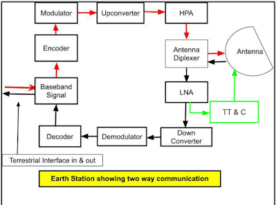
The above block diagram is explained below: Transmit chain: Terrestrial Network: The Earth station is connected to various terrestrial networks and a terrestrial network connected with exchanges and local exchanges. Local exchanges are connected with different modes of communication (voice, data, broadcast, internet etc.). Local exchanges multiplexed different types of signals as per need and compatibility to transmit to main exchanges. After multiplexing It may be 2mbps stream or otherwise. Main exchanges further multiplexed the signals as per requirement to transmit to Earth station. Baseband Signal: The signal received from the terrestrial the network is processed at the Baseband signal unit. In this unit, received signal is demultiplexed, digitized (if it is not already digitized) and Other changes are made as per The need for the next unit i.e. Encoder. Output of the Baseband unit may be like 70 Mhz or 140 Mhz or as desired. Please keep in mind that The Baseband signal unit is the same for Transmission and Receiving the signal. Encoder: It introduces Error Correction Coding to reduce the error rate to the acceptable level. In this unit, extra bits are added to the signal received from Baseband unit to make the signal unique. These extra bits do not have any intelligence or information but Help us retrieve the signal at Receiver end. Modulator: The output of the Encoder is given to the modulator and here signal is modulated as per the need of earth station. In simple terms, modulation means the signal is imposed on the carrier Frequency. Upconverter: Since modulation is generally done at 70 MHz or 140 MHz. You should Remember that modulation is always done at a lower frequency because These frequencies are most suitable for modulation and electronic components or devices are working well at lower frequencies. However for transmitting the signal from earth station to satellite, high frequency (minimum around 6 Ghz, if the satellite is working in C band) is required. High frequency carries high energy, and high energy is required to travel the large distance like 36000 Km for Geostationary satellites. Therefore Upconverter is employed Here to convert the frequency in 6 Ghz range or higher if the satellite is working in another frequency band like Ku. So here is the output of The modulator is mixed with local oscillator frequency to get the desired output. HPA: A High-power Amplifier (HPA) is employed here to amplify the signal up to that level which is suitable to reach the retrievable signal at satellite receive antenna. High-power amplifiers are generally TWTA (Travelling Wave Tube Amplifiers), however, these are now replaced by Solid State Power Amplifiers (SSPA). As the name suggests, these are capable of generating high power which is sufficient as needed. Antenna Diplexer: The output of HPA is given to the Antenna Diplexer. Please keep in mind that Only one antenna is applied here which will handle transmission and Receive signals simultaneously. That is why Antenna Diplexer is needed here and it is capable of avoiding interference in between the outgoing and incoming signals. Antenna: The output of the Antenna diplexer goes to space through the antenna. This antenna may be a dish antenna or a specific antenna as needed. It is once again reiterated that the same antenna is being used for receiving the signal. One important fact is to be known to us i.e. Antenna beamwidth. Here we will not go into much depth, just try to understand what is Beam Width? Beamwidth means the solid conical angle made by the transmitted signal. Here, in this case, it should be a very narrow beamwidth to hit the satellite antenna perfectly without spillover the signal outside the satellite antenna. Receive Chain: Antenna and Antenna Diplexer: As already mentioned in the transmit chain part that the Antenna and Antenna diplexer both are the same for the receive chain. Transmit and receive frequency is always kept different to avoid any interference in between the both, so the same antenna and antenna diplexer are working well for transmitting and receive chain. So the signal transmitted from a satellite is received here at the antenna and After passing through the antenna diplexer, the output is given to LNA. LNA: Low Noise Amplifier (LNA) is always mounted very near or at the feed of the antenna. Because the signal from The satellite is traveling a large distance like 36000 Km (if the satellite is working in Geostationary Orbit) Due to this long distance, The transmitted signal from the satellite suffer a heavy space loss and by reaching at the antenna of the Earth station, it becomes very feeble.
If LNA is placed away from the antenna feed, then it is required to connect with some feeder wire which will again cause heavy loss to the received signal which is already feeble. So the signal may die out before reaching the LNA. Please keep in mind That feeder wire gives heavy loss on Ghz range frequency of satellite communication. As the name suggests, LNA is a special type of amplifier which will amplify the signal but not add or very negligibly add the noise generated by the LNA itself. If the simple amplifier is used at the place of LNA. It will add the self-generative noise with a feeble signal resulting in unretrievable signal. Down Converter: The output of LNA is generally in Ghz range and for modulation, it should be around 70 Mhz or 140 Mhz. The reason for it is already explained in the transmit chain. Therefore the roll of the down converter is just the opposite of the Upconverter. Downconverters change the frequencies in the range of 70 Mhz or 140 Mhz or as desired. Demodulator: Its role is just opposite to Modulator. Here the signal is extracted from the downconverted carrier frequency to feed into the decoder. Decoder: The role of the Decoder is just the opposite of Encoder and it plays a very an important role in the extraction of real signals. Since the signal is traveling a long and passes through various processing units, due to this complex process, it is difficult to maintain the signal in 100% original form as transmitted. The extra bits added during the transmission at the encoder, help us To retrieve the signal correctly even if it is marginally corrupted during the process. So extra bits are added at the encoder end is removed here and the original signal is retrieved and sent to the Baseband signal unit. Baseband Signal Unit: In this unit, the signal is further processed and multiplexed as per The need for the terrestrial interface and distributed to the terrestrial links accordingly. TT&C: Telemetry Tracking and command (TT&C) receives the input data and after amplification at LNA, it is sent back to the satellite. The counterpart of TT&C at Earth station also exists at the satellite end. TT & C at the satellite end checks the parameters of the satellite and sends it to the Control and Command center to correct it accordingly for proper Functioning of Satellite communication. In a nutshell, We can say that the role of TT&C ( at the earth station and on satellite) and Control and Command Centre is to maintain the good health of the satellite for its smooth functioning. |
2. Space Segment- The Space segment means Communication Satellites. It consists of the various components like : Power Supply System: It provides the power supply to the smooth functioning of satellite components through solar panels, and also stores the power supply In the secondary batteries to use When a direct supply of sunlight through the solar panels is not available. TT & C: Telemetry Tracking and Command (TT & C) has the same role as explained in the earth segment section. It exchanges the data between the TT & C and Command center on earth to maintain the good health of the satellite for its smooth Functioning. Altitude and Orbital Control System (AOCS): AOCS uses thrusters and sensors to maintain the orbital location and altitude of the satellite. Transponder: It is the heart of the communication satellite and consists of various communication devices. It is responsible for receiving the signal from the Transmit earth station, process, and retransmit it to the Receive Earth Station. Processing involves the desired modification of signal with the help of various electronic and communication devices inside the transponder. Please keep in mind that the word Satellite is popularly used at the Place of Transponder in general terms and it is adopted here. The transponder may be classified in Two ways as given below: (I) Transparent Transponders: These are also called Bent Pipe Transponders. As names suggest (transparent or bent pipe), Such types of transponders are doing simple functions of frequency translation and amplification. It means they receive a higher frequency signal from the earth stations, Down convert it as desired and after amplification, signal is sent back to earth stations. (II) OBP or Regenerative Transponder: On Board Processing (OBP) or Regenerative as names suggest, Such types of transponders perform much more modern functions in addition to Down conversion and amplification. These special functions maybe like noise reducer, modulation and demodulation, change of mode and modulation, storage & transmission of signal as and when desired, etc., or we can say that the signal is reshaped, retimed, regenerated and retransmitted here. Readers should understand here the benefits of regenerations. Regeneration means noise is removed from the incoming signal and it is extracted in the original form and then amplified, in this way, noise is not amplified With the real signal, and, we will be able to retransmit the signal in more correct way and in turn, it will be retrieved at the earth station with more accuracy. Nowadays, OBP transponders are taking the place of Transparent Transponders. The working principle of a Transparent Transponder is shown in the below diagram And explained thereafter: |
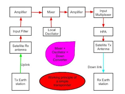
UPLINK and Satellite Receive Antenna: From the Earth station antenna, a signal is sent to the satellite and it is intercepted by the receive antenna of the satellite. The frequency on which This signal is sent, is called Uplink frequency and this path is called uplink. The uplink frequency may be in the range of 6 GHz (if communication is provided in C band) or it may be much higher, if it is working on the Ku band. The uplink signal should be hit to satellite Receive an Antenna in such a way that the signal should not spillover outside the antenna. It should be intercepted by the antenna in total to avoid missing any signal part. For this purpose The beam width of the uplink the signal should be very narrow to hit the satellite antenna. Input Filter: From the receive antenna of the satellite, the signal is given to the Input filter unit. The input filter allows the required frequency range only and rejects the unwanted frequencies. In this way, noise may be limited. Otherwise if unwanted frequencies enter the next unit i.e. Amplifier unit, unnecessary noise will be amplified along with amplification of the desired signal. Amplifier: Since the received signal has traveled a large distance from the earth station to the satellite. Due to space and other losses, the signal received by satellites is always in feeble condition. So amplification is a must at this stage. Downconverter: Since the signal is transmitted at Uplink frequency. It is required to downconvert here to to send back to receive earth station. The downlink frequency is always lower than the Uplink frequency due to the following Few reasons: The low frequency will suffer from low space loss. The low frequency will provide a large coverage area (footprint) on earth to receive the signal. Since satellites have limited power to amplify the signal, with this limited power, the lower frequency can amplify better than the higher frequency. In this unit input of the Downconverter is mixed with the frequency of the local oscillator in such a way as to produce the output of the downconverter as desired by the next unit. Amplifier: The role of amplifiers is the same here in other places. It amplifies the signal. Input Multiplexer: Please keep in mind that a satellite may have 40, 60 or more or less transponders and here only one of the the transponder is shown for example. Similarly, a transponder may have so many downconverters to change The frequencies in a desired way. Here only one downconverter is shown for example. It should be very clear that the frequency output of each downconverter will always be different to avoid any interference in between. These outputs of different downconverters will be multiplexed Here in Input multiplexer to make a stream. HPA: The role of HPA (high power amplifier) is the same here as explained in Earth station segment. It amplifies with high power in such a way so that the signal should be capable of being retrieved at the Earth station. Satellite Transmit Antenna: The Role of the satellite transmit antenna is very important here. We are talking about the beam width of the antenna. It may be narrow like 1 degree beamwidth or it may be large like 17 degree. A narrow-angle means a narrow coverage area (footprint) on the earth. A large angle means a wide coverage area on the earth. If a satellite is located in a Geostationary orbit and beamwidth angle of 17 degrees, It may cover one-third of the earth. Therefore, as per the requirement, the satellite antenna beamwidth angle is adjusted to get the required coverage area on the ground. |
Summary: It is assumed here that the readers of the blog is having elementary knowledge of Electronics and communication. However Technical terms coming in Between the blog are explained briefly as and when it is felt needed. The working principle of Earth station and the transponder is explained in simple terms to give an idea of their functioning. Actual diagrams may be different to meet the demands of the system and it will vary from one communication system to another, for which We have to study separately. |
Disclaimer: The best efforts are made to provide the authentic knowledge of the subject. However, the author does not take any guarantee/responsibility of its correctness and completeness. Readers may cross-check from other sources if needed. The end of this article is here but not the end of learning, Please keep on learning. |
==The End===
- Get link
- X
- Other Apps


Comments
Post a Comment
Thank you, most welcome, 👍